

Technical column
In order to realize a high efficiency motor, I would like to transmit information on the importance of vector magnetic characteristics analysis technology.
This technical column is summarized by editing based on the contents related to "Vector Magnetic Characteristic Analysis" described in the past Mail Magazine column.
table of contents
1. Vector magnetic characterization technology - Prologue -
As a top runner measure of the country aiming for energy saving, from April 2015 it seems that motor manufacturers can only ship products that have cleared the efficiency standard IE 3. However, reality is that about 90% of the motors operated in Japan is IE1. Due to regulations being implemented in the US and Europe as early as possible, IE 3 motors are widely used, and there were many pioneering introductions with IE 4, IE 5 in German motor technology exhibition, Professor Enokizono reported (Fall in 2015 Time). Professor Masato Enoji (emeritus emeritus at Oita University, currently representative of Vector Magnetic Property Technology Institute) is leading vector magnetic characterization technology. Even in this technical column we will quote information from numerous laboratories.
In Japan, efficiency seems to be improved with inverter technology (control), but it seems that efficiency of original motor efficiency was not much focused. Even in IE 3 motors, there are cases where it has responded by enlarging the physique, while in Europe and the United States seems to be challenging high efficiency with a small motor. It is a resolute attitude that the price is high, but it is natural.
Furthermore, if it becomes IE 4, it is difficult unless efficiency of original motor is made, and it comes down to iron loss reduction and improvement of building factor. Even among iron losses, what is necessary for hysteresis loss reduction is vector magnetic characteristics analysis technology (finally connected).
What on Eh? I am going to write it in this technical column from now on. Some places are somewhat inaccurate, so I think that you should keep it in mind.
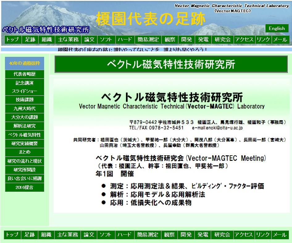
Fig1 Vector magnetic characterization technology laboratory
2. Top runner system and IE 4
Top runner system is the policy policy of the country aiming for energy conservation. For each device with high power consumption, the guideline is to aim for at least the best performance (top runner) at the time of standard setting. Equipment includes passenger cars, freight cars, air conditioners, TVs, videos etc. There are 30 kinds. Among them is a three-phase induction motor, which is a motor used in many industries. Considering that more than half of domestic electricity consumption is consumed by the motor, countermeasures are urgent.
IE 4 is an international standard of motor efficiency level. IE1 (standard efficiency), IE2 (high efficiency), IE3 (premium efficiency), IE4 (super premium efficiency) and so on. In trial calculations, if domestic motors are all replaced with IE 4, domestic electricity consumption will be reduced by 1.5%, CO 2 emissions will be suppressed. It is very important.
The reason why high efficiency motors are not widespread in Japan is that the price of the equipment is high when adopting it, the body size becomes large in order to raise the efficiency, it becomes impossible to set it, the revolution speed rises and the speed reducer and the wiring capacity It seems that the motor manufacturer did not focus on it, as the user was not so enthusiastic. But it will be serious as it will not be exported (China also started to regulate).
I am going to develop why IE 4 development is difficult and how vector magnetic characteristics analysis is useful.
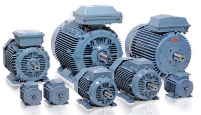
Fig2 Industrial motor
3. Inverter technology and energy saving
We will talk about energy saving effect by inverter technology briefly. If an alternating current is passed through the stator excitation coil of the motor and a magnetic field that rotates spatially is generated inside it, the electromagnet arranged inside rotates accordingly, this is the mechanism by which the motor rotates is). Energy saving operation is possible if it can rotate at high speed when you want to increase the output and can rotate at low speed when the output is low. At this time, the inverter technology is the technology to freely switch the frequency of the alternating current. In fact, it is a control technology that cuts the direct current small and shapes it into the current waveform of the specified frequency. When there was no inverter technology, since the frequency of AC was constant, the output was controlled by turning on / off the current repeatedly. Rather than repeating the dash · holiday, occasionally running with jogging slowly is less image of physical strength consumption. By the inverter technology, the electricity charge of the air conditioner has decreased drastically, it is really wonderful energy saving technology.
However, if we can improve the efficiency of the motor itself, I think that we can keep running at high speed at all times like a marathon runner with less power. This is a high efficiency IE 4 motor. For that reason, it is necessary to develop technologies to reduce wasteful energy = iron loss.
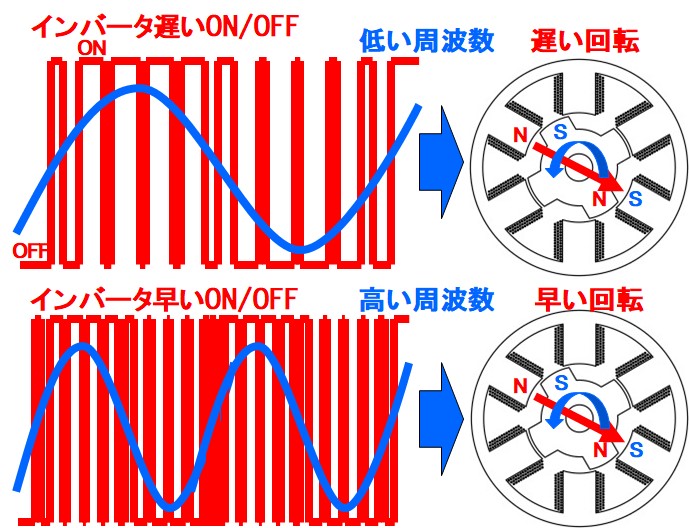
Fig3 Inverter switching and motor rotation speed
4. Will it become IE 3 if I increase my physique?
In "1. Prologue" I wrote that "In Europe and the United States, we are challenging for high efficiency with a small motor, whereas IE3 motors also responded by increasing the size of the body." About this meaning It is a story.
As a rough explanation, the output of the motor is based on the product of the body size (outer diameter and thickness), the magnetic quantity (magnitude of magnetic flux density), the quantity of electricity (the number of windings and the current value of the coil) and the number of revolutions (rotation speed) Become. If the output is the same condition, you can increase the physique, for example to reduce the magnetic mass. Iron loss is proportional to 2 magnitude of this magnetic amount, so loss decreases with the same output = efficiency increases. Another way is to increase the rotation speed to reduce the magnetic amount.
The above is one countermeasure, but as I wrote in "2. Top Runner System", the physique got bigger and it became impossible to set, the number of revolutions increased and the reduction gear became necessary, and it needs attention. If the size of the electric car etc. becomes heavy (heavy), fuel consumption may become worse. Measures to reduce the size and improve efficiency are necessary. One of them becomes a contrivance to lower iron loss of the motor itself.
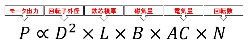
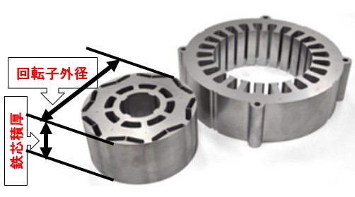
Fig4 Relationship between motor output and physique
5. Electromagnetic steel sheet is excellent
Have you disassembled the motor or transformer? Very thin iron plates are laminated. Since these are devices functioning by the action of magnetism, it is desirable that the magnetism easily passes through and the heat loss is small. Electromagnetic steel sheets have been developed as a material easy to pass through special magnetism. Also, if this is made thin, eddy current that becomes a base of heat generation becomes difficult to flow, thickness is 0.5 ~ 0.2 mm is used. Efforts were made to prevent eddy current from flowing (iron loss is small) as a material, and the efficiency of the motor has dramatically improved in the development of the electromagnetic steel plate.
Iron has a crystal structure and there is a direction easy for magnetism to pass through, this is called easy magnetization direction. Non-oriented electrical steel sheet (NO: Non Oriented) when the magnetization easy direction is random. The thin steel plate is produced by rolling, but the direction of easy magnetization is aligned in this rolling direction is the directional electrical steel sheet (GO: Grain Oriented). GO is used for a transformer where the direction of magnetism is determined, and NO is used for a motor whose direction changes. Material name 50 in 50 A 470 represents plate thickness 0.5 mm and 470 represents iron loss below 4.7 W / kg (50 Hz, 1.5 T). The iron loss value of the material name of the non-oriented electrical steel sheet is 50 Hz at 1.5 T, the iron loss value of the material name of the grain oriented electrical steel sheet is 50 Hz, 1.7 T.
Although it is an extra story, amorphous amorphous metal is produced when it is solidified rapidly from the molten state. Amorphous whose main component is iron has superior characteristics of high permeability and low loss (iron loss is 1 / 10th of that of electromagnetic steel sheet). Just because it is thin and hard, it is used in a transformer, but it seems that it was difficult to use with a complicated shape motor. Recently, usage examples have come up, and expectations for high efficiency motors are increasing.
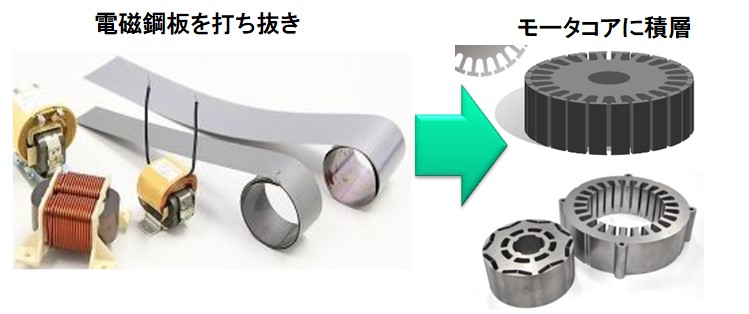
Fig5 Electromagnetic steel plate
6. Attention is paid to vector magnetic characteristics of electromagnetic steel sheets
Although it is an electromagnetic steel sheet which dramatically improved the efficiency of the motor, the speed of remarkable progress seems to have decayed in recent years. Professor Enokizono is said to be a problem of magnetic measurement method of magnetic material.
From here we will leap to the talk of vector magnetic properties, so we will keep on a rough story this time.
The magnetic measurement of the conventional magnetic material was a scalar magnetic property measurement that only looked at the relation between the magnetic flux density in one direction and the magnetic field strength. Specifically, Evistane testers and single plate magnetic testers are used. For directional electromagnetic steel sheets, it is possible to see the anisotropy by measuring 360 degrees with respect to easy magnetization direction, but looking at the relationship between magnetic flux density and magnetic field strength in the same direction is the same.
Actually, the magnetic flux density and magnetic field strength are oriented in the same direction at the same time. This is the vector magnetic property. A rotating magnetic flux is generated inside the motor, but a rotating magnetic field is generated by overtaking it and overtaking it. Knowing this vector relation, it is expected that new characteristics of electromagnetic steel sheet will be visible, improvement of utilization technology and further development of highly efficient motor will be developed. In a series of technical columns, I would like to explain this importance.
By the way, vector magnetic property database of 50A470, 35H440 as NO material and 27P90, 35G155 as GO material can be prepared and analyzed in our vector magnetic property analysis software μ - E & S.
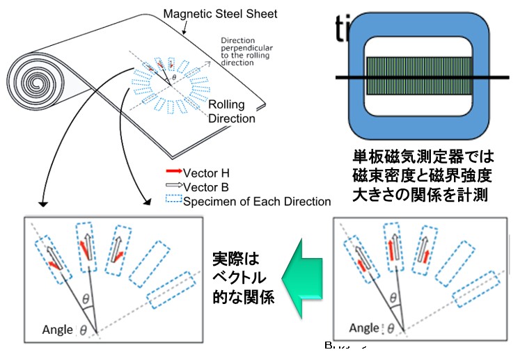
Fig6 磁気測定
7. Measure iron loss
Let's look at iron loss measurement of electromagnetic steel sheet. Representative methods include the Epstein test method and the single plate magnetic test method. Measure the magnetic properties of the electromagnetic steel sheet by cutting out the specimen from the electromagnetic steel plate and measuring the flux density, magnetic field strength, iron loss (using the hysteresis loop area). However, since the H vector and the B vector are parallel components measured under alternating magnetic flux sine wave conditions, it is generally one-dimensional (scalar) magnetic characteristics.
The measurement method of interest here is three ways as a result of the project that Professor Enokizono was represented as representative (JST regional mobility research and development project "Construction of next generation electromagnetic force equipment development technology" 2008 to 2012).
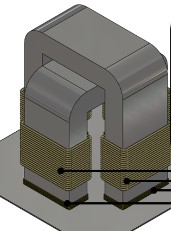
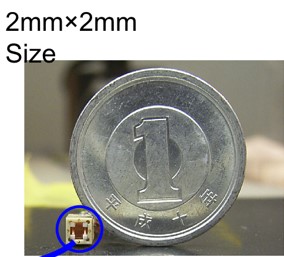
The first is a two-dimensional vector magnetometer. The excitation yokes are arranged in the rolling direction and the direction perpendicular to the rolling direction with respect to the specimen of the electromagnetic steel plate to generate the alternating magnetic flux and the rotating magnetic flux and measure the strength of the magnetic field. As a result, the magnetic property information of the electromagnetic steel sheet leaps from scalar to vector. Currently, Metron Technical Institute is commercializing it as a vector BH tester. The second is a very small local two-dimensional vector magnetic sensor device of the probe method & H coil method. It can be miniaturized to a size of a few millimeters and measure magnetic flux density and magnetic field strength vector and iron loss at arbitrary positions of the motor stator structure. Moreover, it can also obtain the distribution with the rotor incorporated and rotated. Currently, Britech is commercializing it as a vector magnetic characteristic visualization device. Finally, it is an iron loss visualization device using thermographics. This is thought to be handled by the Oita Prefectural Industrial Science and Technology Center.
With these new measurement technologies, the value of further magnetic properties of electromagnetic steel sheets is becoming visible. From now on, technology that effectively utilizes its value will become important.
 |
 |
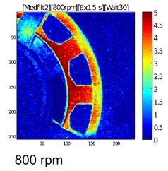 |
Fig7-1 Vector BH tester |
Fig7-2 H coil sensor with ultra small probe |
Fig7-3 Thermo iron loss visualization device |
8. Method for obtaining iron loss by simulation
Let's look at a method to obtain iron loss by simulation. Method 1 is a method to calculate iron loss from Steinmetz formula. It is a typical method of conventional (or present) simulation method, and it is a method to obtain by obtaining a maximum magnetic flux density by multiplying the obtained magnetic flux density by a normal magnetic field analysis. In this method, the maximum magnetic flux density distribution and iron loss distribution are almost similar, but the actual iron loss measurement distribution is different. Although the magnetic characteristics should change depending on the magnitude of iron loss, in view of the fact that we do not consider such things, we are seeking iron loss in a postprocessing manner, so it is stronger to calculate the iron loss more accurately than in the future It is shortage.
Method 2 is a method of hysteresis magnetic field analysis and obtaining iron loss from the loop area. We have realized the hysteresis analysis using the plausacher model in the three dimensional magnetic field analysis package called μ - MF. This requires hysteresis characteristics (many minor loops) of the magnetic material, and calculates hysteresis history for each element according to that information. It is superior to method 1 in terms of performing magnetic field analysis while taking nonlinear magnetic characteristics of hysteresis characteristics into consideration (although it takes time to calculate). However, at present, it is a scalar magnetic characteristic analysis (although anisotropy can be considered).
Method 3 is a vector magnetic characteristic analysis technique that we would like to propose. Inside the motor and the transformer alternating and rotating magnetic flux is generated for each place. Therefore, the magnetic field strength vector for the alternating and rotating magnetic flux vector of the steel specimen will be converted into magnetic characteristic data. The calculation result of vector change according to that information faithfully reproduces the actual magnetic state. Since the hysteresis curve can be drawn faithfully from this calculation result, high accuracy iron loss distribution can be obtained.
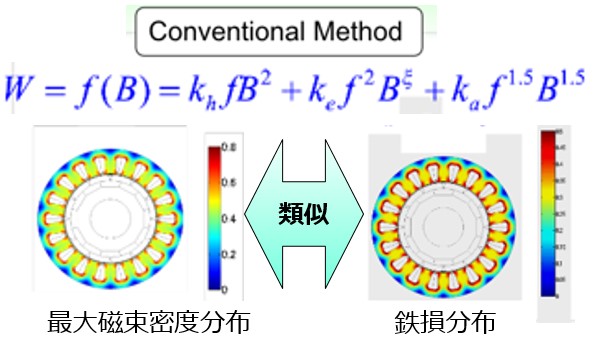
Fig8 Iron loss formula of Steinmetz
9. Prysach model - for hysteresis magnetic field analysis -
Have you ever heard of the Preisach model in the previous chapter? This is one of the mechanisms (models) for performing hysteresis magnetic field analysis. Magnetic materials are magnetized when a magnetic field is applied, but magnetization remains even when the magnetic field is removed. This is a hysteresis characteristic and is represented by a hysteresis curve (loop curve of BH). We will calculate the iron loss from the hysteresis loop area, how much magnetization will be left by the external magnetic field.
Although it is an overview of the mechanism of the prysach model,
Mechanism 1: Consider a function that defines the amount of magnetization M in the range of the saturation magnetic field ± Ha (large around H = 0). This function can be made from many minor loop measurement data for each magnetic type.
Mechanism 2: - The accumulation of the distribution of M above from Ha to H is the magnetization M at the magnetic field H (In this way, the magnetization curve H - M is gradual at first, rapidly rises near H = 0, It becomes loose at the end and it becomes close to actual)
Mechanism 3: The distribution of magnetization M can be calculated from the measured hysteresis curve
Mechanism 4: There is a bit of ingenuity when the magnetic field decreases (Actually distribution is two-dimensional, the boundary to be integrated changes to the right when increasing, downward when decreasing) Please!)
Using the ply saher model, for example, you can also calculate a minor loop curve that increases from a magnetic field and returns to the original magnetic field. Recently we hear well the play model is basically the same mechanism, it is considered to have further developed.
In our company, it is mounted on 3-D FEM software μ-MF. If there is a measured hysteresis curve, you can calculate it very easily and stably. In practice, it is used for influence analysis of residual magnetization on environmental magnetic field and iron loss analysis.
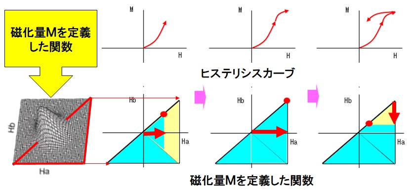
Fig9 Preisach model
10. The difference between the E & S model and the Preisach model
The algorithm called E & S model is used in the 2D vector magnetic characteristic analysis we are dealing with. Dr. Enokizono and his colleagues developed and are still studying. Here is also a hysteresis analysis, but it is a story about where it is different from the Preisach model.
Even though it is isotropic with materials like electromagnetic steel sheets, the magnetic permeability slightly differs in the direction perpendicular to the rolling direction (anisotropy). Furthermore, when the magnetic field is rotating, the H vector and the B vector are misdirected, and the displacement amount changes with the rotation angle. This is the vector magnetic characteristic. The E & S model can take this characteristic into consideration, and as a result can also compute complex hysteresis curves. On the other hand, the Preisach model is a scalar magnetic characteristic model assuming that H vector and B vector have the same orientation. It is a method to calculate the hysteresis curve in this range (Vector Preisach model is currently being studied).
Even in the Preisach model, when the magnetic field changes in one direction, etc., it can calculate accurately including hysteresis loss. However, for example, a rotating magnetic field is generated in the motor yoke, so in order to analyze hysteresis loss and loss distribution with high accuracy, it is necessary to consider vector magnetic characteristics. At this time, the E & S model demonstrates its capabilities, it is just analytical technology for "low loss and high efficiency of the motor".
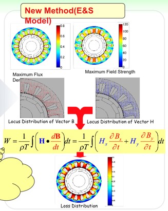
Fig10 E & S model
11. Current status and technical issues of high-speed rotary motors
The electromagnetic study group called the 25th MAGDA Conference (Magnetodynamics Conference, 2016/11/24, 25) was held in Kiryu (Organized by the Japan AEM Society). Starting with the presentation of Dr. Enokizono's "Current status and technical issues of high-speed rotation (HS) motors", we will focus on the announcement related to vector magnetic properties.
In recent years, the world trend seems to be heading for high-speed rotating motors, in order to make the motor smaller and lighter and aim for low loss and high efficiency. As I wrote before, the motor output is proportional to the physique / magnetic flux density / excitation current / rotation number, but since it is desired to reduce the physical size, it is the direction of increasing the magnetic flux density or increasing the rotation speed. However, increasing the number of revolutions will increase the iron loss. The eddy current loss increases with 2 rpm of the rotation number (hysteresis loss is proportional), here the electrical steel sheet is further reduced to 0.05 mm and so on, this is improved for the moment. In this way, the remaining hysteresis loss mitigation measures are important points.
After all, as a result of many case studies, based on the information of the iron loss distribution obtained from the result of vector magnetic characteristics of magnetic flux density and magnetic field strength conforming to the actual measurement, iron loss reduction It is said that it succeeded. Specifically, with a motor of about 100 W, when ironing at 10,000 rpm (500 Hz excitation), the iron loss is reduced by 45% compared with the 0.35 mm material for the plate thickness 0.08 mm material, so further reduction in hysteresis loss is great It means that you can expect an effect.
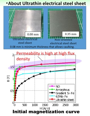
Fig11 Ultrathin electrical steel sheet
12. Building factor?
There are various factors to increase the iron loss of the motor, but the major factor related to the vector magnetic characteristics is the rotational flux of the iron core and the deterioration of the magnetic characteristics generated in the manufacturing process. Although there are punching, lamination, winding insertion, and frame insertion in the manufacturing process, it finally increases to 3 to 5 times the iron loss value of the electromagnetic steel plate. This increase rate is called the building factor, and lowering it is a measure of high efficiency. The greatest deterioration seems to be caused by residual stress being applied to the iron core due to punching, tightening at the time of lamination, crimping at the time of frame insertion, and so on. Therefore, it is important to develop a manufacturing process that lowers the building factor, such as appropriate strain relief annealing before and after the lamination process.
In vector magnetic characteristics analysis, iron loss increase due to rotating flux can be analyzed, but analysis considering the influence of stress is also being studied and reported. Our vector magnetic properties analysis software is still in the former, but we are thinking to make efforts towards possible in the future.
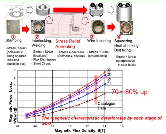
Fig12 Increase in iron loss during manufacturing process
13. To cooperate with measuring instrument manufacturer!
The magnetic properties under the rotating magnetic flux of the electromagnetic steel sheet, as well as the residual stress and magnetic properties in the manufacturing process, the most important thing can be measured and understood. It is only when the simulation is actually measured, it demonstrates its power. Therefore, in order to further develop vector magnetic characteristics analysis technology, we decided to collaborate with a measuring instrument manufacturer (Metron Giken Co., Ltd.).
Metron Technical Institute (Headquarters: Kita-ku, Dojima, Osaka City) is a company that has many achievements in the integration of measurement systems to suit the needs of customers, taking advantage of accumulation know-how of "measurement control". There are many lineups of measuring instruments and controllers, for example AC magnetic testers can acquire scalar hysteresis characteristics and can capture data to JMAG. Even in relation to vector magnetic properties, the vector BH tester can measure vector magnetic properties and core loss under rotating magnetic flux, and can also be imported into the μ-E & S database. In addition, various measurement frames (with compression tensile load function, heating function, stator core support, etc.) corresponding to the building factor are also prepared, and it is effective for grasping by actual measurement.
Based on the synergistic effect of μ-E & S analysis technology and Metron Technical measurement technology, we believe that vector magnetic characterization technology will be useful for development of low loss and high efficiency of motor greatly from now on.
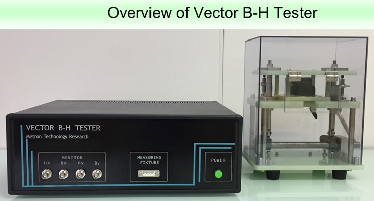
Fig13 Vector BH tester
14. Deployment to dynamic E & S
We have discussed vector magnetic characteristics analysis so far, but this algorithm consists of a static E & S model algorithm. Measured by the vector magnetic property measuring device is a distorted magnetic field strength vector waveform generated when the magnetic flux density vector is excited by a sinusoidal wave. In addition, since the measurement is 50 Hz excitation, eddy current due to 50 Hz is taken into consideration. Using this magnetic flux density B vector and magnetic field intensity H vector, hysteresis curves of x component and Y component can be drawn. Since this hysteresis curve also includes the effect of eddy current of 50 Hz, the area integral of the hysteresis curve is 50 Hz iron loss (hysteresis loss + eddy current loss).
The challenge is the iron loss at frequencies other than 50 Hz. On actual machines, use at higher frequencies is considered. Another problem is correspondence to the distorted magnetic flux density waveform. Since it is a static E & S model that the magnetic flux density is excited by a sinusoidal wave, the basis of the distorted magnetic flux density waveform is to extract the components and refer to the database. The dynamic E & S model addresses these two challenges.
In the dynamic E & S model, the magnetic field strength due to the eddy current of the operating frequency is calculated and corrected using the classic eddy current model (modeling the eddy current in the thin plate). For the distorted magnetic flux density, decompose it into harmonic components, calculate the influence of eddy currents in that frequency component, and correct it. In this way you will be able to simulate more realistic vector magnetic properties relationships.
The dynamic E & S model will be incorporated as a grade-up of μ-E & S soon.
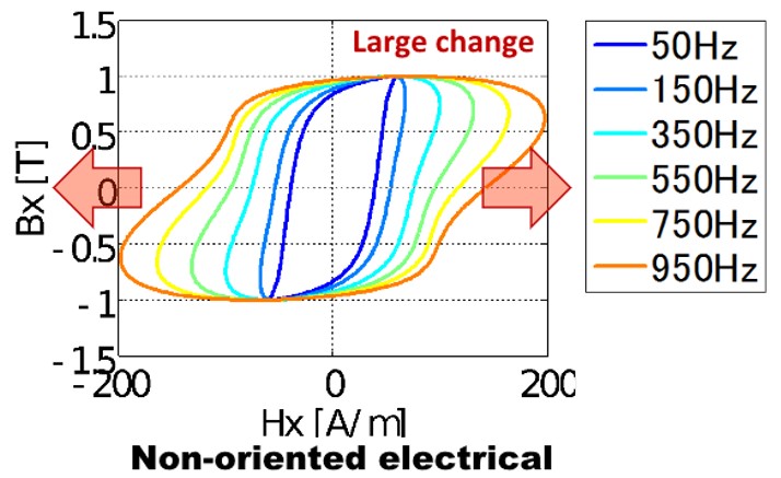
Fig14 Frequency dependence of hysteresis curve
15. Development for visualization of vector magnetic properties
The magnetic characteristics used in conventional scalar magnetic characteristics analysis are BH curves. It is a chart of the relationship between magnetic field intensity and magnetic flux density in a certain direction inside the magnetic material. From this chart, the characteristics of the magnetic material can be grasped by the degree of rise of the initial permeability, the magnitude of the saturation magnetic flux density, and the magnitude of the magnetic field intensity at that time.
On the other hand, it is a bit complicated as it becomes a vector in vector magnetic characteristics. Consider the magnetic flux density vector from the alternating magnetic flux to the rotating magnetic flux, the magnetic field strength vector at this time is composed of information of a pair. 1: The ratio of the maximum value and the minimum value of the rotating flux is defined as the axial ratio α, and α = 1 is a perfect circle and α = 0 can be parameterized as an alternating magnetic flux (even in the case of alternating magnetic flux, the magnetic field intensity has expanded You can express things that draw loops properly). 2: How many times the maximum value vector of magnetic flux density is oriented counterclockwise from the rolling direction (RD direction = rolling direction) of the electromagnetic steel plate, this is the inclination angle θB. 3: When the maximum value of magnetic flux density is 0.1 T and 1.6 T, the magnetic field intensity waveform differs. This is the Bmax parameter. 4: As the magnetic flux density vector rotates, the magnetic field strength vector follows or follows and lags behind, this opening angle is θBH. 5: And when the frequency f changes, a new relation is found. Although only 50 Hz characteristics are stored in the database, the frequency characteristics can be obtained from this information using the dynamic E & S model. There are five possible parameters.
Rotating magnetic flux and alternating magnetic flux are generated in each place of the motor and the transformer. For each location the parameters above apply and the magnetic field waveform is estimated (iron loss can be estimated). Conversely, if the iron loss characteristics can be seen for each parameter, it will lead to estimating the cause of the large iron loss. As you can think about avoiding saturation from the BH curve, we can expect to consider the iron loss reduction (We are planning to make a dissemination with technical information on the homepage in the future).
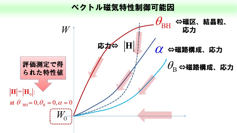
Fig15 Study on iron loss reduction by various parameters